Reverse-engineering the Unilux thermostat
I recently moved to Toronto, into a high-rise condo -- the glass-tower kind where you own everything from the paint inward and nothing past it. About the only thing in the unit I actually get to control is the climate, and I've been automating my home long enough that the first thing I do anywhere new is figure out what I can talk to.
That planning starts before I have the keys. I want to know, well in advance, exactly what's bolted to the walls, so I can decide what stays, what gets replaced, and what I'll need to take apart. Which is how, a month out from move-in, I ended up texting a friend who already lived in the building.
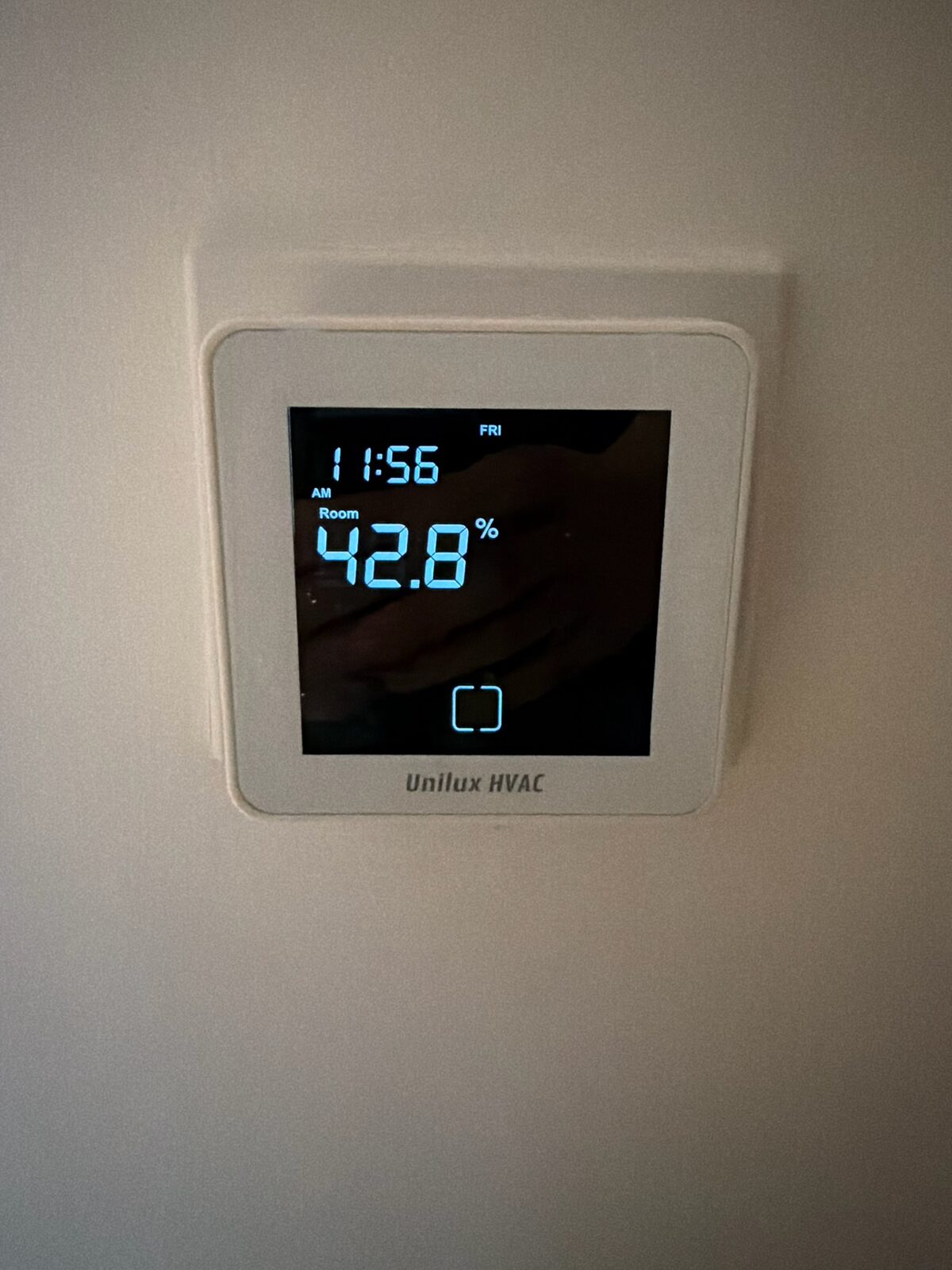
Me: Can you do me a favor when you get the chance. Trying to plan ahead with home automation stuff. Can you take a picture of your AC/heating thermostat
[a photo of the thermostat arrives]
Him: Ur gonna brick your AC before you move in 😭😭
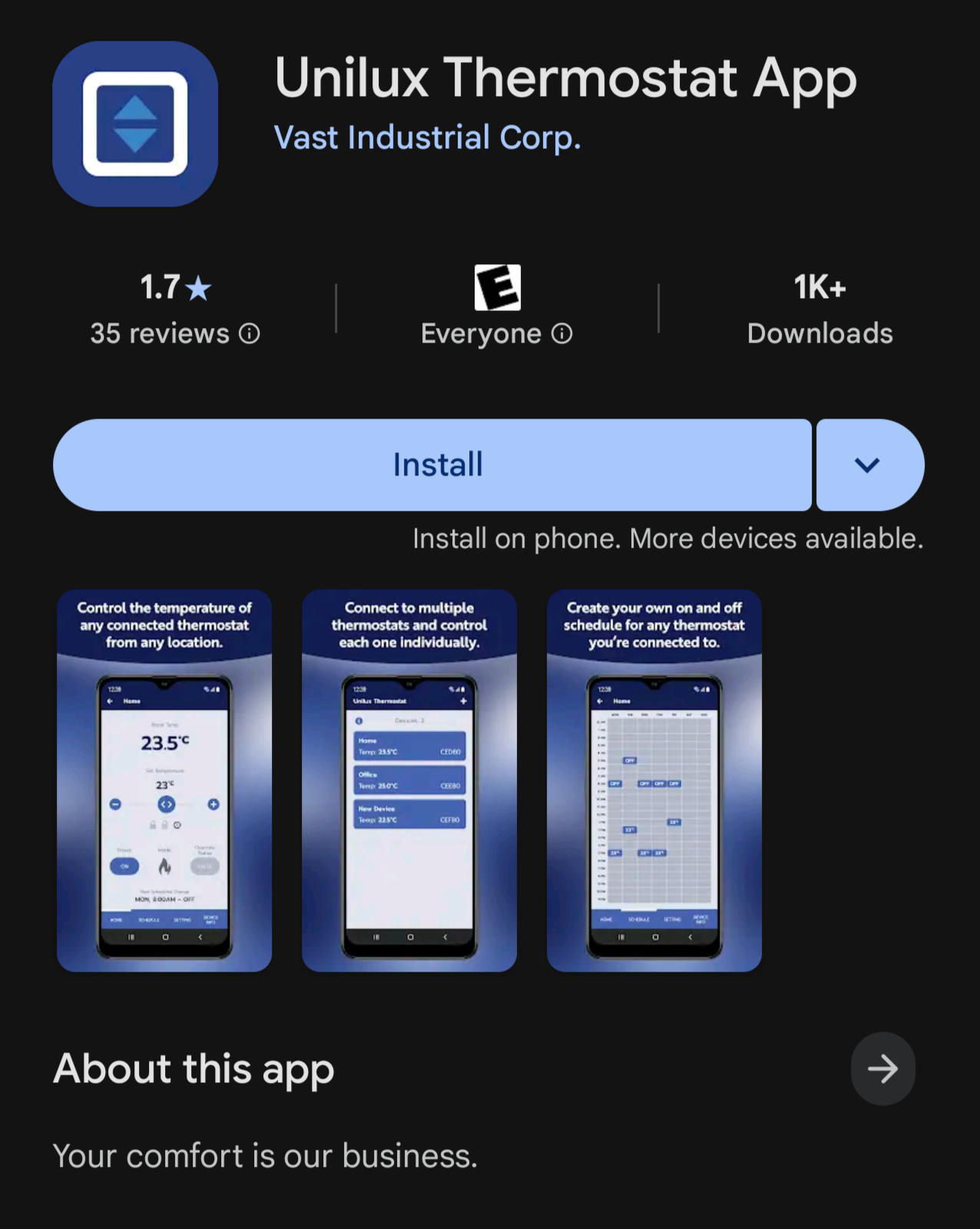
He wasn't wrong about my intentions. The unit did come with a fan-coil thermostat wired into the in-slab hydronic loop, and it shipped with a phone app. The app was, to put it kindly, not good: flaky cloud connections, limited features, and a vendor lock-in I had no interest in living with.
My first instinct was the usual one: pop the cover off, see whether I could bypass the whole thing and drive the relay from an ESP8266 of my own. So I unscrewed the faceplate, and... that's not what I found.
There was already an ESP32 inside
Behind the capacitive-touch front panel there were two boards. The first was the actual thermostat controller -- the MCU that reads the floor/room sensors, drives the fan-coil actuators, and runs the schedule. The second was a tiny Wi-Fi daughterboard sitting on a header, and silkscreened across it was the giveaway: an Espressif ESP32.
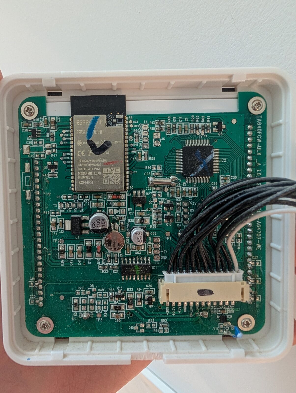
So the architecture was already split into two:
- a thermostat MCU that owns the hardware, and
- an ESP32 whose entire job is to be a cloud bridge -- relaying commands between the vendor's MQTT broker and the thermostat MCU over a private serial link.
That was a much better outcome than I'd hoped. I didn't need to reverse the relays or the sensors. I just needed to understand the conversation between the ESP32 and the thermostat MCU, replace the ESP32's firmware with something I controlled, and join that conversation myself.
But before I could do that, I needed the stock firmware -- both as a backup and as the source of truth for how that serial link actually worked.
Dumping the firmware
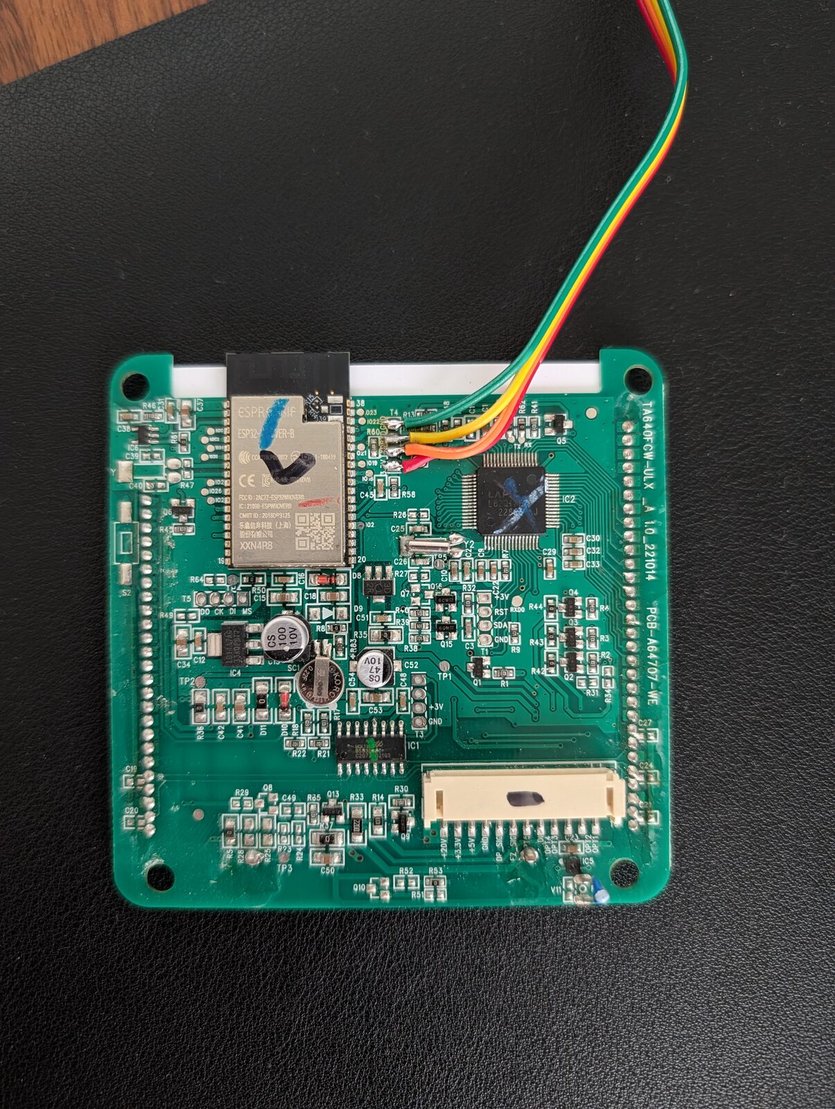
The ESP32's flash is reachable over its UART0 boot console, but only if you can
hold GPIO0 low at reset and get a TX/RX/GND/3V3 onto the board. The
daughterboard exposed a row of unpopulated through-hole pads for exactly this,
so I tinned them and soldered four wires to a USB-to-TTL adapter.
With the chip in download mode, esptool did the rest -- a full 4 MB read of
the SPI flash:
esptool.py --port /dev/ttyUSB0 --baud 460800 \
  read_flash 0 0x400000 firmware.bin
I now had the entire flash in one blob: bootloader, partition table, the app image, NVS, and a SPIFFS filesystem. First priority: back it up somewhere safe. Second priority: take it apart.
An AES S-Box
First, binwalk:
$ binwalk firmware.bin
DECIMAL       HEXADECIMAL   DESCRIPTION
----------------------------------------------------------------
167528        0x28E68       SHA256 hash constants, little endian
286188        0x45DEC       AES S-Box
----------------------------------------------------------------

Analyzed 1 file for 85 file signatures (187 magic patterns) in 27.0 ms
Two hits. The second is the AES S-Box -- the 256-byte substitution table at the center of AES, and the classic sign that the image might be encrypted on the flash.
But this is an ESP32 running a Wi-Fi client with MQTT over TLS. WPA2 is AES-CCMP, TLS is AES-GCM, SHA256 runs through both -- the constants are there for network crypto, which doesn't require the application image to be encrypted.
Entropy across the full 4 MB dump:
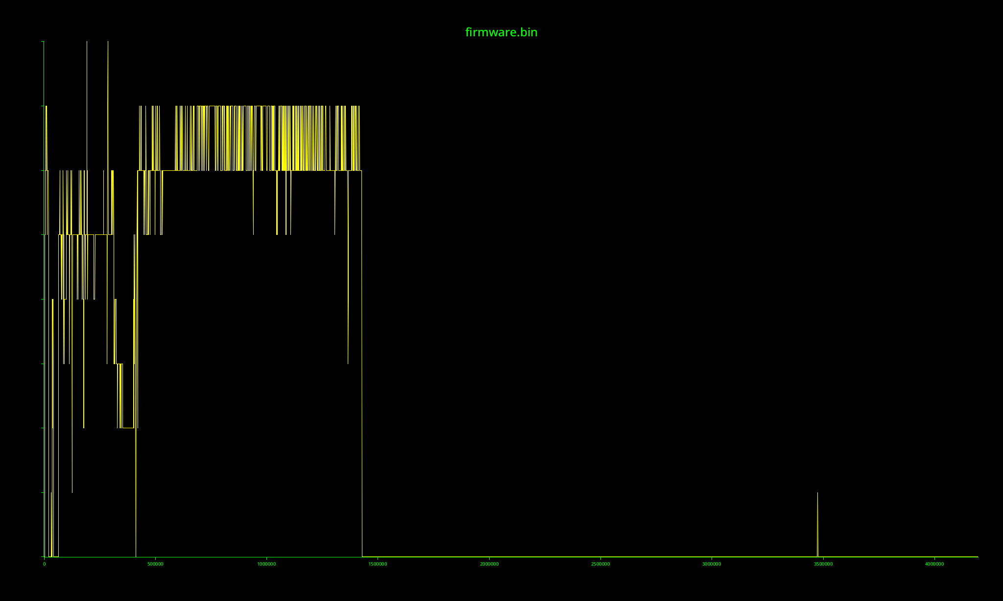
The app image sits around 6-7 bits per byte -- high, but choppy, with code and
data regions visible, never pinned at the 8.0 ceiling. After the app partition
the curve drops to zero: the back two-thirds of the dump is erased flash
(0xFF). Average entropy across the 4 MB is ~3.2 bits per byte, and no 64 KB
block reaches the ceiling. Encrypted flash sits at ~8.0 wherever there's data;
this doesn't.
The strings were plaintext, and everywhere:
C:\Users\dc\AppData\Local\Temp\arduino_build_491448\sketch\src\Common\AUP\AUP.cpp
WMMM_RECV(%s):floorTemp=%d, %f
Send Msg(WMMM_WIFI_STATUS): mode=%d(1:STA/2:AP), ...
task_simplewmmmlink_handle(): begin...
Nothing encrypted leaves Windows Arduino-IDE build paths and printf format strings readable in the binary. Whoever built this ("dc", on a Windows machine, in the Arduino IDE) shipped it with debug logging compiled in, and those log strings did most of the work from here. The S-Box was a red herring.
Splitting the image and loading it into Ghidra
The 4 MB dump isn't one blob -- it's the raw SPI flash with Espressif's
partition layout laid out at fixed offsets. The partition table itself lives at
0x8000: a flat array of 32-byte entries, each giving a name, type, offset, and
size. Reading it gave me the whole map at a glance:
name      type   off         size
nvs       data   0x9000      0x5000
otadata   data   0xe000      0x2000
app0      app    0x10000     0x1a0000   <- ota_0, the running firmware
app1      app    0x1b0000    0x1a0000   <- ota_1, the OTA slot (empty)
spiffs    data   0x350000    0xb0000
That's exactly the layout binwalk had already sniffed out from its signature
scan, so the two agreed -- a nice cross-check. Carving app0 out of the dump
was then a single slice at its offset and length:
dd if=firmware.bin of=app0.bin bs=4096 skip=16 count=416 # 0x10000, 0x1a0000
app0.bin is the main application image, 1.7 MB, and it starts with 0xE9 --
the Espressif app-image magic. The OTA slot beside it (app1) was erased to
0xFF, which told me the device had never taken an over-the-air update: the
factory firmware in app0 was the only copy on the chip, so backing it up
mattered.
The image isn't a flat blob either. Right after the 0xE9 magic it carries an
entry point (0x40084c28) and a small table of six segments, each listing its
own load address and length -- the read-only data, the IRAM/DRAM, and the
flash-mapped code. That table is the whole reason an ESP32 image can be turned
back into an ELF with its sections at the right addresses, instead of a
shapeless megabyte starting at zero:
esptool.py --chip esp32 image_info app0.bin # prints each segment's load addr + len
Pointing a bin-to-ELF conversion at that segment table -- one ELF section per
segment, each dropped at its real load address (flash code mapped at
0x400d0000, IRAM up at 0x40080000) -- produced a proper app0.elf.
With a real ELF in hand I created a Ghidra project for the app0.elf, pointed
it at the Xtensa ESP32 processor, and let auto-analysis run. Then a small
headless script walked every function and decompiled it to a file I could grep:
from ghidra.app.decompiler import DecompInterface, DecompileOptions
from ghidra.util.task import ConsoleTaskMonitor

decomp = DecompInterface()
decomp.setOptions(DecompileOptions())
decomp.openProgram(currentProgram)

fm = currentProgram.getFunctionManager()
for func in fm.getFunctions(True):
    result = decomp.decompileFunction(func, 60, ConsoleTaskMonitor())
    if result and result.decompileCompleted():
        out.append("/* === %s @ %s === */\n%s" % (
            func.getName(), func.getEntryPoint(),
            result.getDecompiledFunction().getC()))
One big grep-able C file.
Decompiling: a second UART, and a protocol called "AUP"
First grep: uart. The ESP32 runs two UARTs:
- UART0 -- the boot/programming console I'd soldered onto.
- UART1 -- a private link to the thermostat MCU.
The private link is driven by a chunk of code whose log strings call it AUP ("Arduino UART Protocol"). It's a simple framed, length-prefixed format:
| Offset | Size | Field | Notes |
|---|---|---|---|
| 0 | 1 | Magic[0] | 0x5A |
| 1 | 1 | Magic[1] | 0x9E |
| 2 | 1 | Checksum | sent as 0 on the wire |
| 3 | 1 | Flag | 0x00 |
| 4 | 1 | Type | 0x01 |
| 5 | 1 | Command | app-layer message type (0x10 = WMMM) |
| 6 | 2 | Length | payload length, big-endian |
| 8 | N | Payload | N bytes |
The decompiled AUP parser walks the receive buffer looking for the 5A 9E sync
marker, reads the big-endian length, waits until the whole frame is present, and
dispatches byte [5] (the command) to a registered handler. Stripped of
Ghidra's noise, the dispatch is just:
// for each registered handler (up to 3):
if (handler.cmd_id == frame[5] && handler.cb != NULL) {
    handler.cb(handler.ctx, frame + 8, length);
    break;
}
And the matching aup_send builds a frame by calloc-ing length + 8 bytes,
writing the magic, copying the payload in, byte-swapping the length field, and
pushing it out the UART. Symmetric and simple.
Inside command 0x10 lives a second, nested protocol the logs call WMMM
("Wireless MCU Message Manager"). Every WMMM message starts with a one-byte
message id and three reserved bytes, then a type-specific payload. The debug
strings had already handed me the vocabulary -- WMMM_ROOM_TEMP,
WMMM_SETPOINT_VALUE, WMMM_ALL_CONFIG, WMMM_WIFI_STATUS, and a few dozen
more -- and the decompiled wmmm_msg_parse was one giant switch over those
ids.
Finding the MCU UART pins in the binary
UART1 talks to the MCU, but on which GPIOs? The header had more pins than I wanted to probe blind.
The answer was in the AUP initialization. aup_init takes a config struct, and
the caller fills it in right before the call:
config.uart_num  = 1;          // UART1
config.baud      = 0x1c200;    // 115200
config.rx_pin    = 5;          // GPIO5
config.tx_pin    = 4;          // GPIO4
config.buf_size  = 0x200;      // 512 bytes
aup_init(&config);
115200 8N1, GPIO4 = TX, GPIO5 = RX.
Sniffing the bus with ESPHome
I flashed an ESPHome build onto the ESP32 with a UART component on those pins and the debug logger on, so every byte from the MCU dumped to my console in hex:
uart:
  tx_pin: GPIO4
  rx_pin: GPIO5
  baud_rate: 115200
Then I poked the thermostat and watched the logs. Setpoint up: a frame appears. Back down: another frame, one byte different. The MCU broadcasts state changes over the link whether anyone's listening or not.
One captured frame, decoded:
5A 9E  00  00  01  10  00 04  2A 00 00 00 00 D7 00 00
└───┘  └┘  └┘  └┘  └┘  └───┘  └─────────────────────┘
magic  ck  fl  ty  cmd  len        WMMM payload
Command 0x10 (WMMM), message 0x2A, payload 00 D7. 0xD7 in tenths of a
degree is 21.5 °C -- my setpoint. WMMM_SETPOINT_VALUE.
Iterating between the logs and the decompilation
wmmm_msg_parse had ~40 message ids, and each only made sense once I'd seen it
on the wire. The loop:
- Poke the thermostat -- change a mode, adjust a fan speed, set the clock.
- Read a frame off the ESPHome logs.
- Find its message id in the decompiled switch and read what that handler did with the payload -- which bytes it byte-swapped, which "observable" property it wrote to, which log string it printed.
- Name it, write it down, repeat.
The debug strings named the fields and their types. A handler logging
WMMM_RECV(%s):floorTemp=%d, %f says the field is floorTemp and the value is
a float -- the %f meant the wire integer gets divided by 10.0, and the
byte-swap calls meant big-endian on the wire.
A few representative results, after enough passes:
| ID | Name | Dir | Payload |
|---|---|---|---|
0x02 |
ROOM_TEMP |
MCU → ESP | two BE i16 temps × 0.1 °C (floor, room) |
0x21 |
CTRL_MODE |
both | one enum byte |
0x2A |
SETPOINT_VALUE |
both | BE i16 setpoint × 0.1 °C |
0x5C |
SET_CHANGEOVER_MODE |
ESP → MCU | one enum byte |
From notes to a library and an ESPHome component
I wrote the protocol up as a reference, then as a C++23 library --
unilux-uart -- implementing
both layers:
- an incremental, byte-at-a-time AUP decoder/encoder that reassembles frames from an async UART stream (and round-trips them losslessly), and
- a WMMM layer that turns each frame into a typed message --
Temperature,TargetTemperature,Mode,FanSpeed,AllConfig,Schedule, and so on -- with a singlestd::variantto dispatch on.
Because the decoder and encoder are exact inverses, every message round-trips byte-for-byte, which makes the whole thing testable offline with captured frames:
// decode a captured frame, then re-encode it -- same bytes back
if (auto msg = unilux::decode_message(frame)) {
  std::visit([](auto &&m) { /* m.t1, m.setpoint, m.mode, ... */ }, *msg);
}
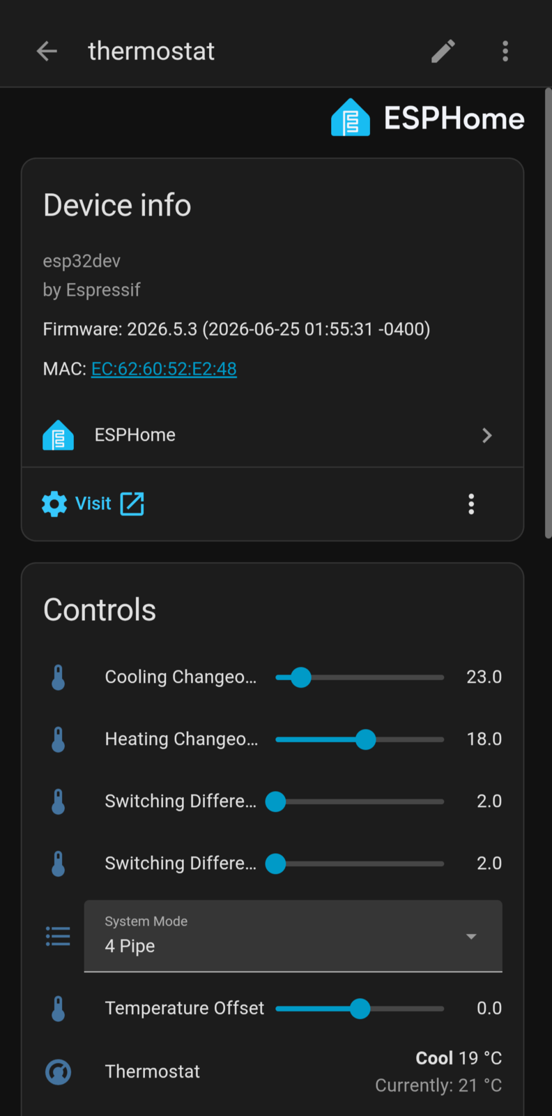
On top of the library I wrote an ESPHome external component (unilux_uart)
that wires it into Home Assistant. Out of the box it surfaces:
- temperature sensors for the floor and room channels,
- a two-way climate entity -- drag the setpoint in Home Assistant and it
transmits a
0x2Aframe; the thermostat reports a new setpoint and it updates the other way, - number entities for the scalar settings (switching differentials, changeover temperatures, temperature offset), and
- select entities for the enum settings (system mode, display unit).
Dropping it onto the device is just:
external_components:
  - source: { type: git, url: https://github.com/dangreco/unilux-uart }
    components: [unilux_uart]

uart:
  tx_pin: GPIO4
  rx_pin: GPIO5
  baud_rate: 115200

unilux_uart:
  t1: { name: "Indoor Temperature" }
  t2: { disabled: true }
  climate:
    name: "Thermostat"
    visual: {
      min_temperature: 5 °C,
      max_temperature: 40 °C,
      temperature_step: 0.5 °C,
    }